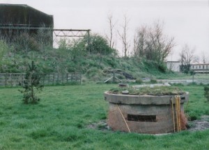
Pickett-Hamilton Fort in elevated position at Silloth Airfield, Cumbria. Photograph by John Minns
Key Facts
- Circular with three Loopholes,
- Hidden when lowered
- Placed in landing areas on airfields
 The `Lifting & Turning Fort`
In the summer of 1940 many engineering companies approached government departments with plans for defence structures designed to their own specifications. The New Kent Construction Company of Ashford, submitted plans for a “disappearing pillbox” for airfield defence to the designs of Donald Hamilton FSI, LRIBA.
The turret of a Pickett-Hamilton Retractable Fort, fully raised and manned by a bren-gun team of the Coldstream Guards, taken on a fighter airfield in Southern England.
ROYAL AIR FORCE FIGHTER COMMAND, 1939-1945 © IWM (CH 17890) IWM Non Commercial Licence
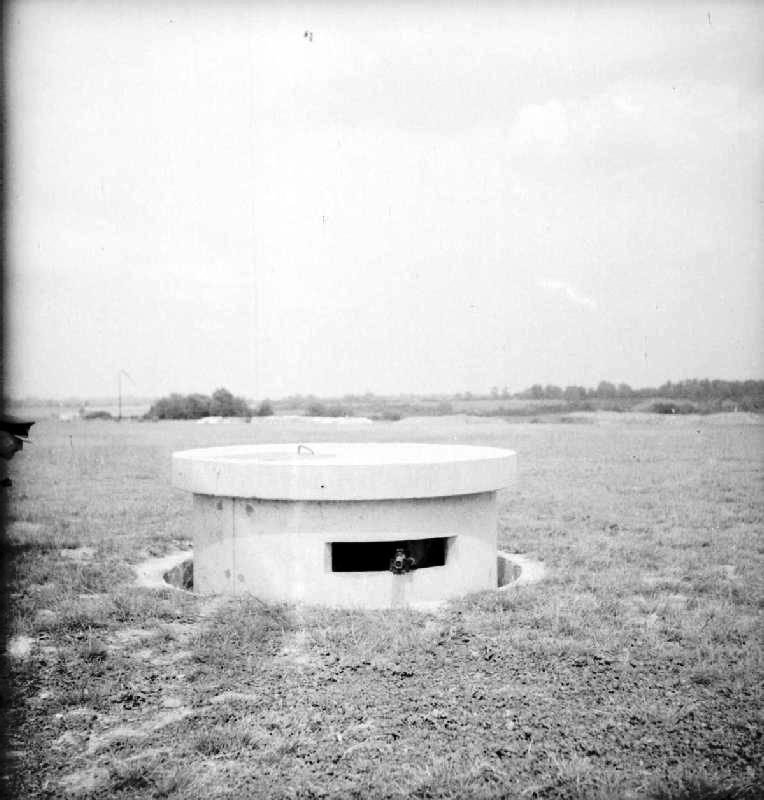
The design consisted of two pre-cast concrete pipes, one sliding within the other, one end of each being closed. These were to be installed on end in the ground at suitable locations on the landing areas of airfields. When not in use, the concrete lid of the smaller pipe (rising head) lay flush with the ground surface, but when brought into action during an emergency, it rose some 2ft 6in above the surface to permit fire from any of its three loopholes. In the closed position the pillbox was concealed, it therefore allowed for an element of surprise particularly in the event of a landing of enemy parachute or airborne troops.

Picket-Hamilton Fort in closed position
The lifting mechanism consisted initially of a standard 8-ton aeroplane jack, but as this took 3 minutes for the head to rise, it was replaced by a compressed air system supplemented by a hand pump for emergency use (which was quicker to operate).
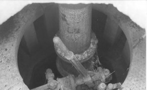
Lifting Mechanism – 8 Ton Aeroplane Jack
This pillbox became known as the Pickett-Hamilton Fort and adopted by the Air Ministry (drawing number 13313/40).
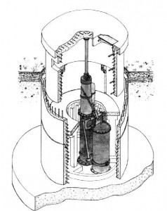
Isometric Sketch Of Pickett-Hamilton Fort. Copyright `Pillboxes` By Henry Wills
The provision and installation of these pillboxes was given the highest priority, the Prime Minister himself showing an interest in the progress of the work. They were soon however, considered obsolete and provision was discontinued. The main reasons were as follows:
- The structures were not sufficiently large to accommodate modern weapons.
- They were not strong enough to sustain the weight of heavy aircraft.
- No upward view was possible (apart from cursory looks through the entrance hatch).
Pickett-Hamilton forts were due to be delivered on 31 January 1941 and in a statement prepared by the New Kent Company on 24 April 1942, out of a total of 335 installations, three had been installed at Middle Wallop.
One of the three standard Pickett-Hamilton forts at Middle Wallop has been found at NGR 3002 3824 (Monument 535)
By Paul Francis Airfield Archaeologist